Field Installer Guide

Pebble Physical Install + Device Setup Guide

Use this guide after the portal setup has been prepared. It covers field installation, device connection, sensor testing, troubleshooting, and final close-out.

Before using this field guide

Confirm the portal is ready

Portal Setup Guide

Required before the installer starts

  • Monitoring Device exists in the portal.
  • Device Serial is visible.
  • Link Code is visible and available to the installer.
  • Physical site timezone has been selected.
  • Main Tank is linked or ready to be linked.
  • Main Tank Sensor Type is selected correctly.

Optional items that must be done first if used

  • Reserve Tank setup is complete if the installation uses a reserve tank.
  • Tank Objects / Additional Measurements are configured if the tank shape requires them.
  • Manual Level Input is disabled if a Reserve Tank is being used.
  • For Pebble Plus, RS485 sensor addresses and wiring plan are known.

Important: The Monitoring Device is the portal record. The Pebble Unit is the physical hardware. The Link Code connects the physical unit to the portal record.

Field workflow

Recommended install sequence

  1. 1
    Confirm the portal is ready.

    Do not start the physical setup without the Link Code and tank configuration.

  2. 2
    Plan the physical installation.

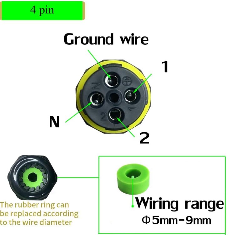
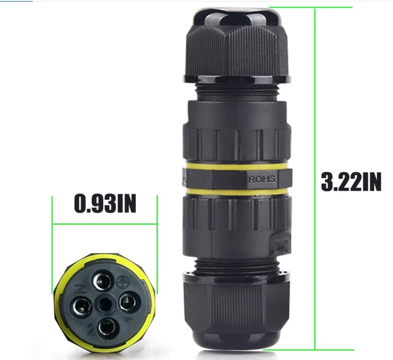
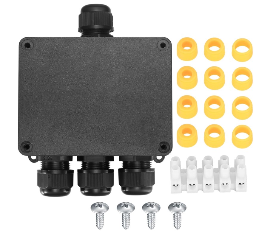
    Choose sensor, controller, cable, junction box, antenna, and power locations before drilling final holes.

  3. 3
    Temporarily power and test position.

    Connect enough to test Wi-Fi signal and sensor direction before final mounting.

  4. 4
    Open Pebble setup mode.

    Press and release the menu button, connect to Pebble-xxxxxx, and open 192.168.4.1.

  5. 5
    Connect to site Wi-Fi and use the Wi-Fi Meter.

    Confirm the planned mounting location has reliable signal before tightening everything down.

  6. 6
    Link device and complete sensor setup.

    Enter the Link Code, choose sensor settings, test readings, and save settings.

  7. 7
    Confirm the portal receives the expected reading.

    Check level value, time, sensor type, and tank relationship before leaving the site.

  8. 8
    Finish Setup.

    Close the temporary setup Wi-Fi and return the device to normal runtime mode.

Hardware Installation

Choose model and confirm the package

The hardware steps change depending on whether this is eco1, eco2, or Pebble Plus.

Pebble eco1 controller
Pebble eco1
One ultrasonic sensor / one tank
Ultrasonic sensor
Ultrasonic sensor
Direct sensor connection

Confirm included

  • Pebble controller
  • One ultrasonic sensor
  • Sensor cable / extension if supplied
  • Power supply or solar kit
  • Tank-top switch if included

Portal match

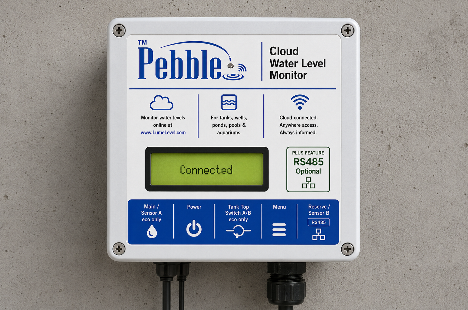
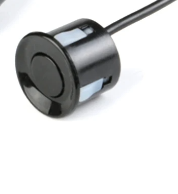
Main Tank should be linked to the Monitoring Device. Sensor Type should be Ultrasonic unless the installation was specially configured otherwise.

Pebble eco2 controller
Pebble eco2
Main + Reserve ultrasonic monitoring
Main ultrasonic sensor
Main sensor / Sensor A
Reserve ultrasonic sensor
Reserve sensor / Sensor B

Confirm included

  • Pebble controller
  • Main ultrasonic sensor
  • Reserve ultrasonic sensor
  • Sensor cables / extensions if supplied
  • Power supply or solar kit

Portal match

Main Tank must be configured as having a reserve. Main Tank is Sensor A / reading 1. Reserve Tank is Sensor B / reading 2.

Pebble Plus controller
Pebble Plus
RS485 bus / advanced sensor installation

Select Plus sensor type

Confirm included / known

  • Pebble Plus controller
  • RS485 sensor or sensors
  • RS485 trunk cable
  • Weatherproof junction boxes
  • Termination plan
  • Unique RS485 addresses

Portal match

The portal sensor type and physical sensor type must agree. If a submersible sensor is used, the portal tank must be set as Submersible.

Hardware rule: Plan the cable route, controller location, and Wi-Fi/antenna location before drilling final holes.

Physical work

Hardware installation steps

Use these accordions as the physical field checklist. Only open the sections that apply to the installation.

Choose a controller location before final mounting. The location should balance sensor cable length, service access, power, and reliable communication.

  • Close enough to the tank for clean cable routing.
  • Accessible for service after installation.
  • Protected from direct spray, flooding, and physical damage.
  • Not mounted directly against a metal tank or metal wall where possible.
  • Away from pumps, dense wiring, large metal surfaces, and large water mass where possible.

Use the Wi-Fi Meter before final mounting: Temporarily power the unit, connect to the site Wi-Fi, and check the Wi-Fi Meter. Target -75 dBm or better where possible. Below -80 dBm should be treated as unreliable.

Optional external antenna

  • Use when the enclosure location gives weak signal or is near metal, water mass, pump rooms, or thick walls.
  • Mount the antenna in the clearest practical location.
  • Keep it vertical and away from metal where possible.
  • Keep coax short, avoid sharp bends, and weather-seal penetrations.
  • Use the Wi-Fi Meter to compare locations before final tightening.
  • Mount the sensor above the water and aim it straight down.
  • Avoid tank walls, ladders, pipes, inlet flow, foam, turbulence, and internal obstructions.
  • Keep the sensor face clear.
  • Record the sensor height and confirm it matches the portal tank setup.
  • Weatherproof the tank-top connection and provide strain relief.

eco2 note: Main sensor connects as Sensor A / reading 1. Reserve sensor connects as Sensor B / reading 2.

Ultrasonic sensor
Ultrasonic sensor
Waterproof junction box
Junction box / strain relief
  • Lower the sensor into the water so the sensing end is near the bottom reference point.
  • Keep the sensor off heavy sludge, sand, or debris where possible.
  • Secure the cable so the sensor cannot swing into a wall, pump, ladder, or inlet.
  • Do not coil excess cable tightly in the wet area. Secure extra cable in a dry, serviceable location.

Portal match: When using a submersible sensor, the portal tank Sensor Type should be Submersible. High Water Overflow is treated as the full/usable level and Sensor Height is handled accordingly.

Cable path

  1. Cable exits tank area.
  2. Cable enters weatherproof junction box or housing.
  3. Use strain relief at the junction box entry.
  4. Route cable to the Pebble controller.
  5. Use strain relief at controller enclosure entry.

Rules

  • Do not let the cable hang from solder joints or connectors.
  • Use strain relief at every enclosure entry.
  • Keep joins inside the junction box.
  • Use drip loops where exposed to weather.
  • Avoid sharp bends, moving tank parts, and pinch points.

Recommended behavior: Tank top closed = switch circuit closed / continuity present. Tank top open = switch circuit open / no continuity.

Before connecting

  1. Test the switch with a meter.
  2. With the magnet in the tank-closed position, confirm continuity.
  3. Move the magnet away and confirm open circuit.
  4. Mount securely so vibration or lid movement does not create false readings.

After connecting

  1. Enable the tank-top switch in Sensor Setup for the correct reading.
  2. Close the tank top and confirm Pebble shows Closed.
  3. Open the tank top and confirm Pebble shows Open.
  4. On Pebble Plus, correct switch polarity/invert setting if the meaning is reversed.

Avoid this: Do not intentionally install the tank-closed condition as an open circuit. A broken wire could then look the same as a normal closed tank.

  • Use a true daisy-chain line.
  • Do not use star wiring.
  • Use one twisted pair for RS485 A/B.
  • Terminate only at the final device on the bus.
  • Each RS485 device must have a unique address.
Open RS485 Wiring Guide
IP68 junction box
IP68 junction
RS485 junction box
Bus wiring connections
12V power adapter
12V DC adapter
Solar power kit
Solar example

Before power-up

  • Correct polarity.
  • No exposed wiring.
  • Cable glands tight.
  • Junction boxes closed.
  • Sensor connected.
  • RS485 A/B checked if Plus.

After the hardware is installed, continue to the Device Setup tab to connect Wi-Fi, link the unit, test readings, configure reporting, and finish setup.

Local setup

Device setup flow

These are the on-site setup steps after the hardware has been planned or mounted enough for testing.

Quick setup details

Setup Network
Pebble-xxxxxx
Setup Password
setup1234
Setup Address
http://192.168.4.1

Normal phone warning: Your phone may say the Pebble setup Wi-Fi has no internet. That is normal. Stay connected until the setup step is complete.

What you will see on screen

Login / Home

Start here after connecting to the temporary Pebble setup Wi-Fi.

Link Device

Enter the Link Code from the portal to bind the physical unit.

Connection Setup

Set Wi-Fi, mobile/APN where applicable, and update timing.

Sensor Setup

Choose sensor type, test readings, and save sensor settings.

  1. 1
    Press and release the Pebble menu button.

    Do not hold the button. This opens the temporary setup Wi-Fi.

  2. 2
    Connect your phone or laptop to Pebble-xxxxxx.

    Use the setup password shown above.

  3. 3
    Open http://192.168.4.1.

    If the page does not open automatically, type the address into the browser.

  4. 4
    Log into the local setup page.

    Use the setup access code. setup1234

  1. Open Connection Setup.
  2. Select the site Wi-Fi network.
  3. Enter the site Wi-Fi password and save.
  4. After Pebble joins the site network, open the Wi-Fi Diagnostics / Wi-Fi Meter.
  5. Move the controller or antenna until the signal is acceptable before final mounting.

RSSI guide

  • -50 to -60 dBm: Excellent
  • -60 to -70 dBm: Good
  • -70 to -75 dBm: Acceptable
  • -75 to -80 dBm: Weak; improve if possible
  • Below -80 dBm: Unreliable

Pebble can keep its setup Wi-Fi open for the installer while also connecting to the site Wi-Fi in the background. Finish Setup closes the temporary setup Wi-Fi.

Link Device

Use Link Device when linking one physical Pebble slot to one Monitoring Device. Enter the Link Code from the portal.

Link All Slots

Use Link All Slots on Pebble Plus when one physical unit is being linked to up to three Monitoring Devices. Each slot uses its own Link Code from the portal.

Important: If Link All Slots says internet is required, return to Connection Setup and connect Pebble to the site Wi-Fi first.

  • Choose the matching quick setup if one applies.
  • Confirm the sensor type for each reading.
  • Confirm the physical sensor setup matches the portal Tank Sensor Type.
  • For ultrasonic sensors, confirm the sensor is mounted above the water and aimed straight down.
  • For submersible sensors, confirm the correct electrical/RS485 version was selected and wired correctly.
  • If a tank-top switch is used, confirm closed and open states.

RS485 service tools

Use RS485 service tools only when an RS485 device needs address recovery, bus-speed correction, zero-offset correction, diagnostics, or switch-box service.

Open RS485 Guide

  • Use the test button to confirm a live reading appears.
  • If using eco2, test both Main and Reserve readings.
  • If a tank-top switch is used, test closed and open states.
  • If assigning addresses on an RS485 bus, connect only one sensor at a time while doing that step.
  • For analog installs, confirm the live electrical value and calibration points.
  • Save settings after all readings and service actions are confirmed.
  • Send an update when the level changes by: Optional level-change based reporting in addition to normal timing.
  • Last check-in time for the day: Default is 2350 hours unless changed.
  • Send updates every hours: Choose how often the device should send updates.

Before leaving the job site, confirm the website has updated with the expected value and timestamp.

Final checks

  • Wi-Fi Meter is preferably -75 dBm or better.
  • Monitoring Device is linked to the correct Main Tank.
  • Timezone is correct.
  • Portal sensor type matches physical setup.
  • Reading appears on the portal with expected timestamp.
  • All settings are saved.

Finish Setup

Finish Setup closes the temporary Pebble setup Wi-Fi and returns the device to normal runtime mode. Use it only after Wi-Fi, linking, sensor setup, and final checks are complete.

Finish Setup does not generate Link Codes, claim slots, erase Wi-Fi credentials, release hardware, or clear the cloud link.

Troubleshooting

Fast checks before deeper troubleshooting

Wi-Fi / cloud

  • Confirm site Wi-Fi name and password.
  • Confirm RSSI is preferably -75 dBm or better.
  • Confirm internet/DNS/HTTPS is available.

Link Code

  • Confirm code is current and from the correct Monitoring Device.
  • Regenerate code if expired.
  • For Plus, confirm the intended slot.

Sensor

  • Check sensor power and wiring.
  • Check sensor type in portal and device setup.
  • For RS485, check address, A/B polarity, bus speed, and termination.

Device screen / LED status

Use the screen message and LED pattern together to decide the next action.

Normal ready state: READY on line 1 and Standby on line 2. During setup, you may see SETUP / 192.168.4.1 or SETUP / WiFi cfg depending on the step.

Screen Line 2 LED Pattern Meaning Installer action
SETUP192.168.4.1Slow blinkDevice is in setup AP mode.Connect to setup Wi-Fi and open setup page.
SETUPWiFi cfgSlow blinkDevice is in Wi-Fi configuration mode.Finish Wi-Fi setup and save site network details.
WIFIConnectingMedium blinkConnecting to Wi-Fi.Wait. If it does not connect, check Wi-Fi details and signal strength.
WIFI ERRCheck WiFiSlow blinkWi-Fi connection failed.Re-enter Wi-Fi details and try again.
UNBOUNDClaim devSlow blinkDevice is not linked.Open Link Device and enter the portal Link Code.
CLAIMClaimingMedium blinkLink request in progress.Wait for completion.
CLAIMOKBoundSolid ONDevice link completed successfully.Continue setup or link another Plus slot if needed.
CODEERRRegen webDouble blinkLink Code expired or invalid.Generate a new Link Code in the portal.
CLAIMERTry againDouble blinkLink failed.Retry and confirm Link Code and selected slot.
CLOUDRetryDouble blink + pauseCloud service could not be reached.Check internet access, DNS, and firewall / HTTPS access.
API ERRRetryTriple blink + pauseServer returned a non-success response.Retry first, then review backend logs if needed.
BADRESPRetryTriple blink + pauseUnexpected server response.Retry, then verify firmware and backend response format.
RESOLVERetryDouble blink + pauseResolve step failed after network connection.Retry after confirming Wi-Fi and cloud connectivity.
SENSERRCheck sensFast blinkSensor problem detected.Check wiring, sensor type, address settings, and power.
TIMEOUTRetryFast blinkSensor did not respond in time.Inspect cabling and communication wiring.
READYStandbySolid ONNormal ready state.No action needed.

Moving or re-linking a physical Pebble

  1. In the portal, open the old Monitoring Device and choose Release Hardware.
  2. On the physical Pebble, open Clear Cloud Link.
  3. Generate fresh Link Codes for the new Monitoring Device or devices.
  4. Use Link Device or Link All Slots to bind the physical Pebble again.

LED pattern guide

  • Slow blink = about 0.8 second interval
  • Medium blink = about 0.35 second interval
  • Fast blink = about 0.12 second interval
  • Solid ON = normal ready state
  • Double blink = grouped pair of flashes
  • Triple blink + pause = grouped triple flashes followed by a pause

Replacement note: Start Replacement is only for replacing the physical board while keeping the same logical Monitoring Device and tank history. Do not confuse it with moving or re-linking hardware.